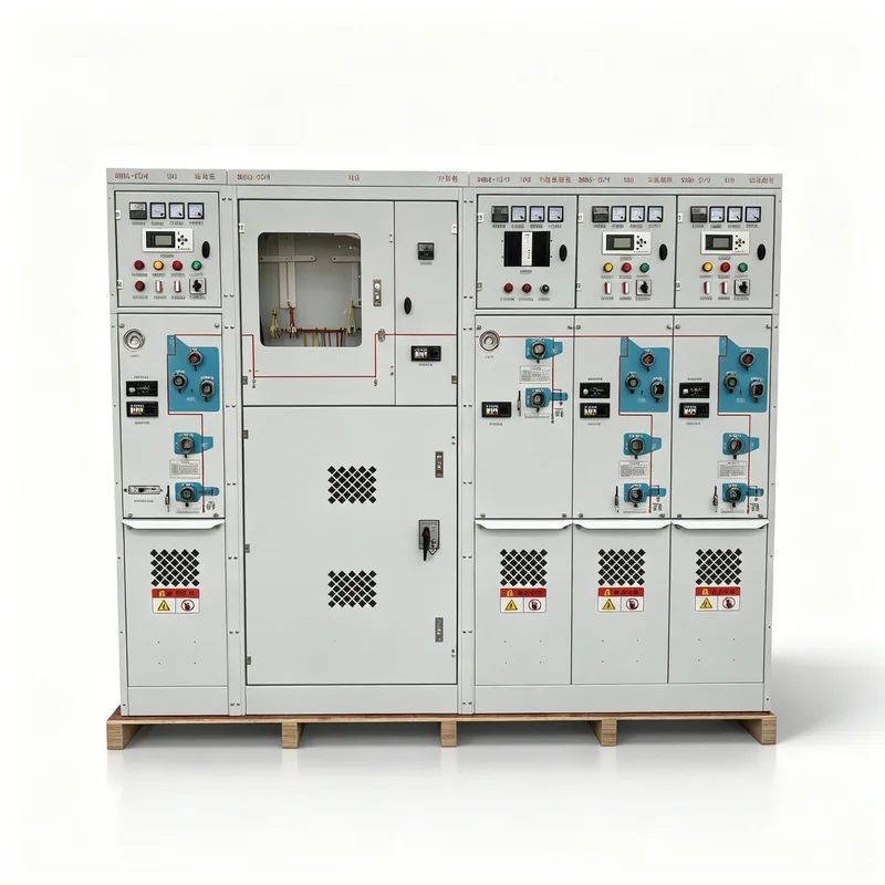
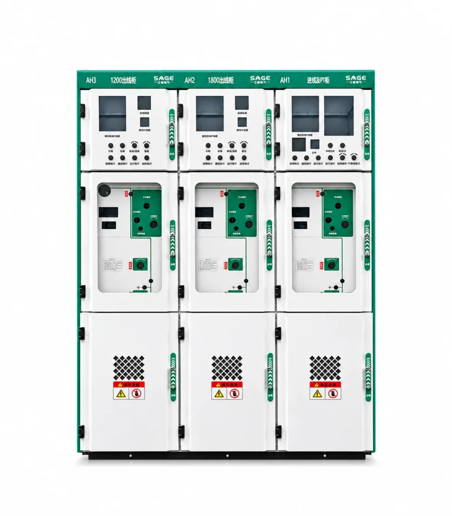
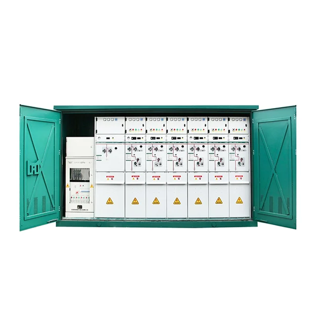
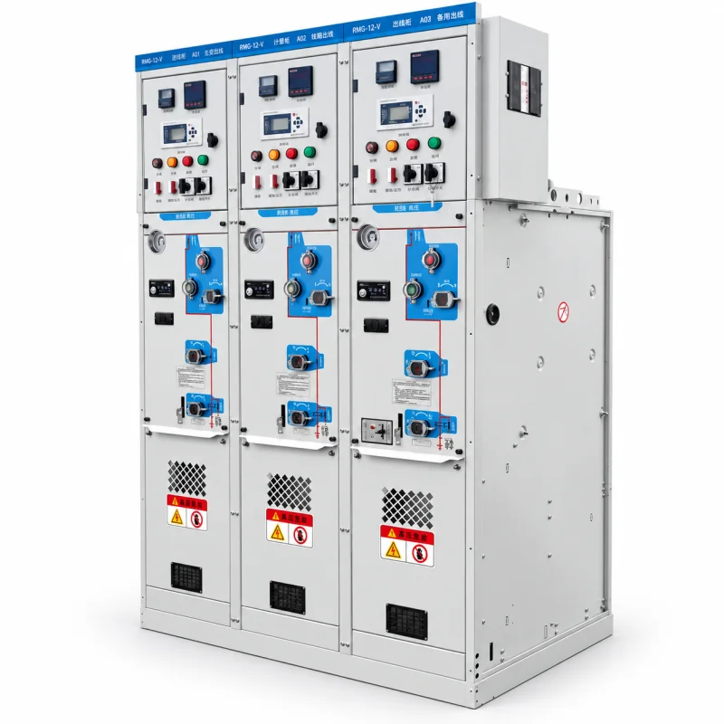
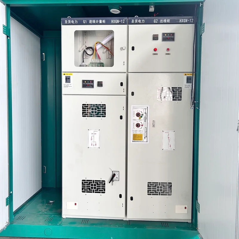
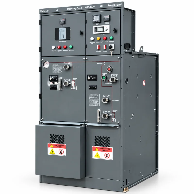
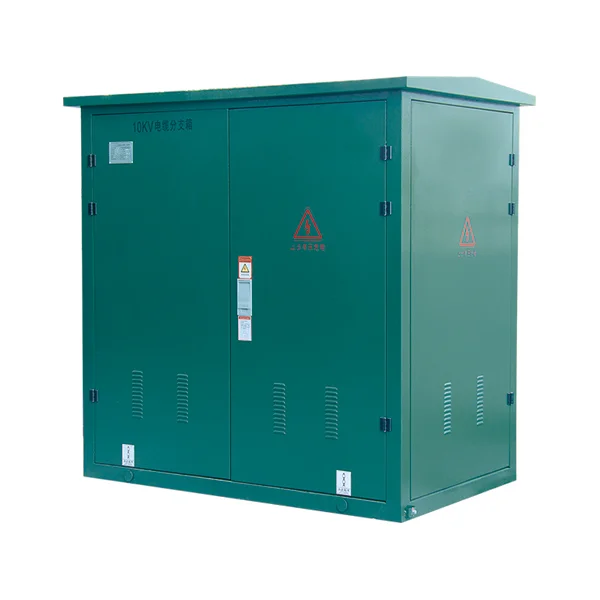
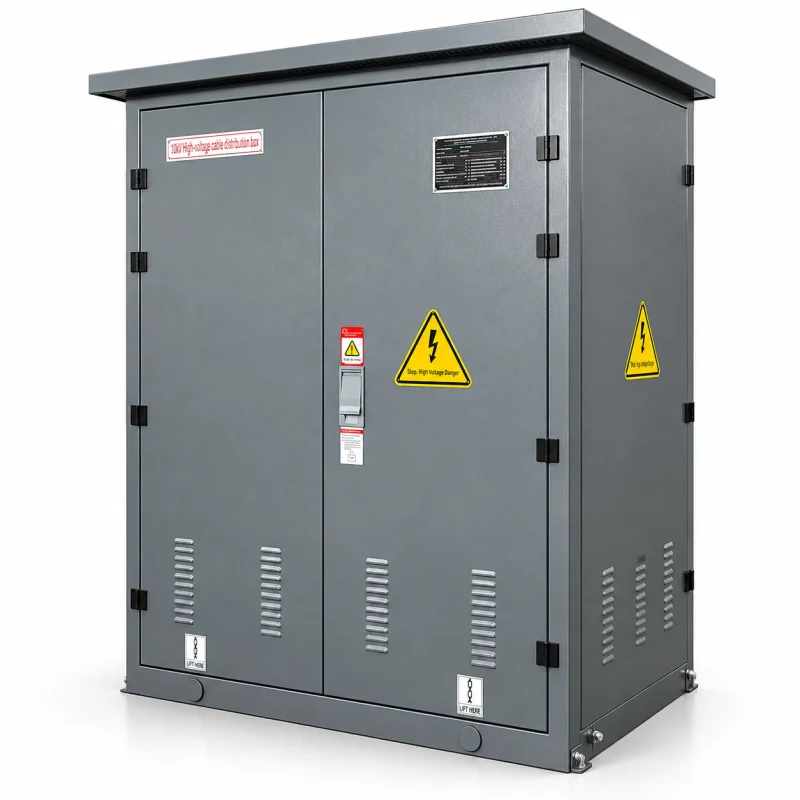
Ring Main Unit Buying Guide | Modules, Insulation and Ratings
1. Map the ring network and the transformer tee-off
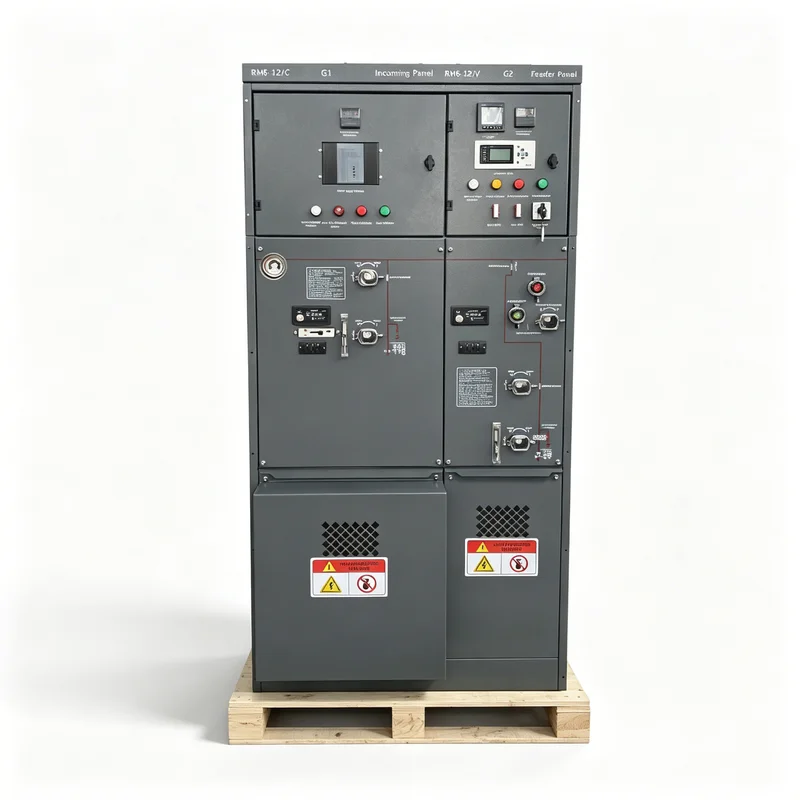
Start with the network diagram and count the circuits: two ring cables in and out, plus one or more transformer tee-offs. Then confirm:
- Rated voltage: 12kV or 24kV, with the corresponding insulation level
- Rated current of ring and tee-off circuits, commonly 630A or 1250A
- Short-time withstand current and duration
- Transformer capacity to be protected by the fuse or breaker
- Whether metering, PT or remote control is required
2. Choose the module combination
| Module | Function | Typical use |
|---|---|---|
| C | Load break switch with earthing switch | Ring incoming and outgoing circuits |
| F | Fuse-switch combination | Transformer protection up to a few hundred kVA |
| V | Vacuum circuit breaker | Larger transformers, feeder protection, automation |
| PT / metering | Voltage transformer and metering | Billing, indication and protection supply |
Fuse protection is simple and economical for small transformers; a vacuum breaker is better where the transformer is large, where reclosing is needed, or where remote control and protection settings are required.
3. Decide the insulation technology
SF6 units are compact, fully sealed and maintenance-free, with a proven insulation and arc-control record. SF6-free gas-insulated units use dry air or nitrogen where regulations or customer policy restrict SF6. Solid-insulated designs suit space-limited, humid or corrosive sites and avoid gas handling entirely. Confirm the global warming potential reporting your project requires before choosing.
4. Check the enclosure and installation conditions
Confirm indoor or outdoor installation, ambient temperature range, altitude, humidity and pollution level. Sealed stainless-steel tanks rated IP67 tolerate flooding and dust, but cable access, foundation height and ventilation still matter. Verify cable entry direction, cable size range and whether front access only is needed for a back-to-wall layout.
5. Specify protection, control and automation
State the fuse ratings and striker type, the breaker protection relay, CT ratios, auxiliary supply and communication protocol. If the unit will be remotely controlled, confirm the RTU or FTU interface, the signal list and the motorised operating mechanism. Define the interlock scheme so that earthing can only be closed with the switch open.
6. Confirm tests, gas data and documentation
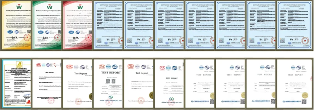
Our RMUs are designed and tested to IEC 62271-200 and GB 3906. Routine tests cover gas tightness, main circuit resistance, power-frequency withstand, mechanical operation and wiring. Documentation should include the outline drawing, single-line diagram, gas pressure and filling record, nameplate data and routine test report.
7. RFQ checklist
- Network diagram and module combination
- Voltage, current and short-circuit ratings
- Transformer capacity and protection type
- SF6, SF6-free or solid insulation
- Indoor or outdoor, ambient and IP requirements
- Metering, PT, automation and communication needs
- Required standards, tests and certificates
- Quantity, cable sizes and delivery date