What Is a Power Substation? Types, Parts and How It Works
Published: Author: JellyDai
A power substation is a facility in the electricity grid where voltage is changed and power flow is switched, protected and controlled. It links the transmission network that moves bulk power over long distances with the distribution network that serves homes, businesses and industry.
That is the short answer to “what is a power substation.” The rest of this guide explains what a substation does, the main types, what is inside one, and how a transmission substation differs from the compact, factory-assembled units used on local distribution feeders.
What Is a Power Substation?
A substation is a node in the electrical generation, transmission and distribution system. Its core job is to transform voltage — either stepping it up for efficient long-distance transmission or stepping it down to a level that distribution lines and equipment can use safely. Many substations also interconnect two networks that operate at different voltages, or provide a point where lines can be switched and a fault can be isolated.
Power rarely travels from a generator to a socket in one step. It may pass through several substations at different voltage levels along the way, which is why substations appear at the boundaries between transmission, sub-transmission and distribution. Major industrial or commercial customers often own and operate their own substations as well.
Most substations are unattended. They rely on protection relays for automatic fault clearing and on SCADA (supervisory control and data acquisition) systems so that operators can monitor and switch the site remotely from a control centre.
What a Power Substation Does
Although designs vary widely, most substations perform some combination of the following functions:
Voltage transformation — step-up transformers raise generator voltage for transmission, while step-down transformers reduce transmission voltage to sub-transmission or distribution levels.
Switching and routing — circuit breakers and switches connect or isolate lines, transformers and feeders so power can be routed around outages or maintenance.
Protection — current and voltage transformers feed relays that detect faults and trip the associated breaker, limiting damage and keeping the rest of the grid stable.
Voltage and power-factor control — capacitors, reactors and voltage regulators keep voltage within limits and correct power factor, especially on long or heavily loaded circuits.
Metering and monitoring — instrument transformers provide the measurements used for billing, indication and automated control.
Interconnection — a substation can tie together separate networks or voltage levels, allowing power to be shared between them.
Main Types of Power Substations
Substations are usually classified by the job they do in the network. The table below summarises the common types before each is described briefly.
Type
Primary role
Typical voltage context
Transmission substation
Connects transmission lines and changes transmission voltages
High and extra-high voltage
Distribution substation
Steps transmission or sub-transmission voltage down to distribution
Medium-voltage output
Collector substation
Gathers power from many generators, such as a wind or solar farm
Medium-voltage collection, stepped up for the grid
Converter substation
Changes current type or frequency, for example AC to DC
HVDC and traction applications
Switching station
Switches lines at one voltage without transforming
Single voltage level, no transformer
Mobile substation
Temporary or emergency supply, mounted on a trailer
Lower rating than a permanent site
Transmission substations
A transmission substation connects two or more transmission lines and may contain transformers to change between transmission voltages. Where all lines are at the same voltage, it acts mainly as a switching point. Larger sites can include voltage-control equipment, phase-shifting transformers and extensive protection and control systems.
Distribution substations
A distribution substation takes power from the transmission or sub-transmission system and reduces it to a medium voltage suitable for local feeders. Those feeders then run along streets — overhead or underground — to distribution transformers near the customer premises. Distribution substations are also a common point of voltage regulation and fault isolation. Medium-voltage distribution classes vary by region, but they generally sit in the low kilovolt to roughly 36 kV range.
Collector substations
In distributed generation projects such as wind and solar farms, a collector substation gathers the output of many turbines or inverters and steps it up for the grid. Power flow is effectively reversed compared with a conventional distribution substation: energy arrives from many small sources and leaves through the transmission connection.
Converter and switching stations
Converter substations use power electronics to change current type or frequency, and are associated with HVDC links and some traction supplies. A switching station is a substation without transformers, operating at a single voltage level; its job is to connect, isolate and reroute circuits quickly when a fault or maintenance requires it.
Mobile substations
A mobile substation packages a transformer, breakers and buswork on a road-legal trailer. It is used for temporary supply during emergencies, planned outages or construction, and it is normally rated lower than the permanent installation it replaces.
What Is Inside a Power Substation?
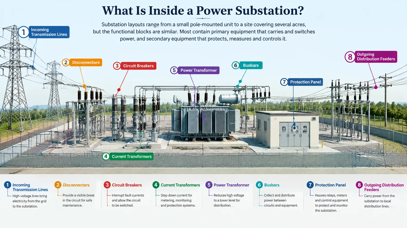
Substation layouts range from a small pole-mounted unit to a site covering several acres, but the functional blocks are similar. Most contain primary equipment that carries and switches power, and secondary equipment that protects, measures and controls it.
Primary equipment
Power transformers — the largest items on most sites, changing voltage between levels. They may be oil-immersed or dry-type depending on rating, location and fire risk.
Circuit breakers — interrupt fault current and normal load current. Vacuum and SF6 designs are common at medium and high voltage.
Disconnectors and earthing switches — provide visible isolation and a safe earth connection before work begins. Disconnectors cannot break load current, so they are operated only after a breaker has opened.
Instrument transformers — current transformers (CTs) and voltage transformers (VTs) scale down high currents and voltages to safe, measurable levels for relays and meters.
Busbars — the common conductors that tie incoming lines, transformers and outgoing feeders together, usually in three phases.
Surge arresters — divert lightning and switching surges to earth to protect insulation.
Capacitors, reactors and regulators — where voltage support or power-factor correction is required.
Protection, control and auxiliary systems
Protection relays — interpret CT and VT signals and trip breakers to isolate faults. Modern digital relays also record events and communicate over station networks such as IEC 61850.
SCADA and remote control — connect the substation to a control centre for monitoring, alarm handling and remote switching.
Auxiliary supply — batteries, chargers and low-voltage boards that keep protection and control working even when the main supply is lost.
Earthing system — a buried conductor grid and earth rods that limit touch and step voltages and provide a safe return path for fault current.
Control building and enclosures — house panels, relays and metering, and set the site’s environmental and security rating.
How a Power Substation Works
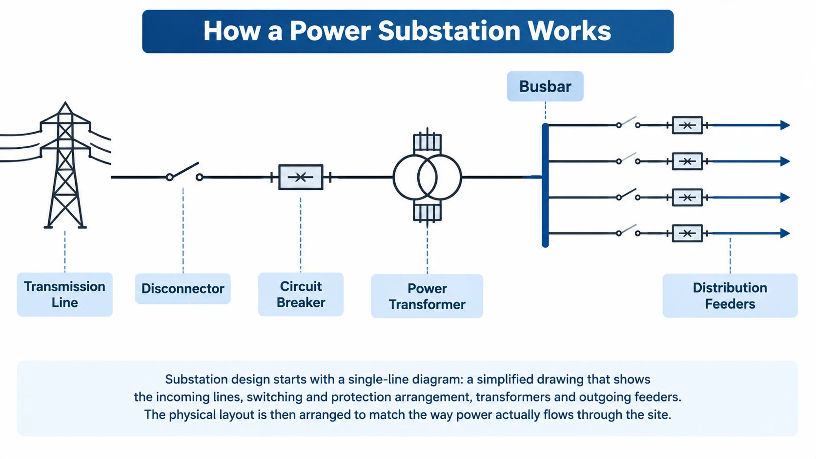
Substation design starts with a single-line diagram: a simplified drawing that shows the incoming lines, switching and protection arrangement, transformers and outgoing feeders. The physical layout is then arranged to match the way power actually flows through the site.
In a typical circuit, an incoming line passes through a disconnector for isolation and a circuit breaker for protection. Current transformers measure the current and feed a relay; if a fault is detected, the relay trips the breaker to isolate the faulted section. The line then connects to a busbar, from which it feeds a transformer and, on the other side, the outgoing distribution feeders. Switching and protection equipment — and increasingly the whole station — can be operated locally or from a remote control centre.
The way breakers and busbars are arranged determines how much of the site stays energised during maintenance. Simple stations may use a single bus, while critical ones use a ring bus, double bus or breaker-and-a-half arrangement so that no single breaker failure interrupts supply to other circuits.
Substation Terms You Will See in a Specification
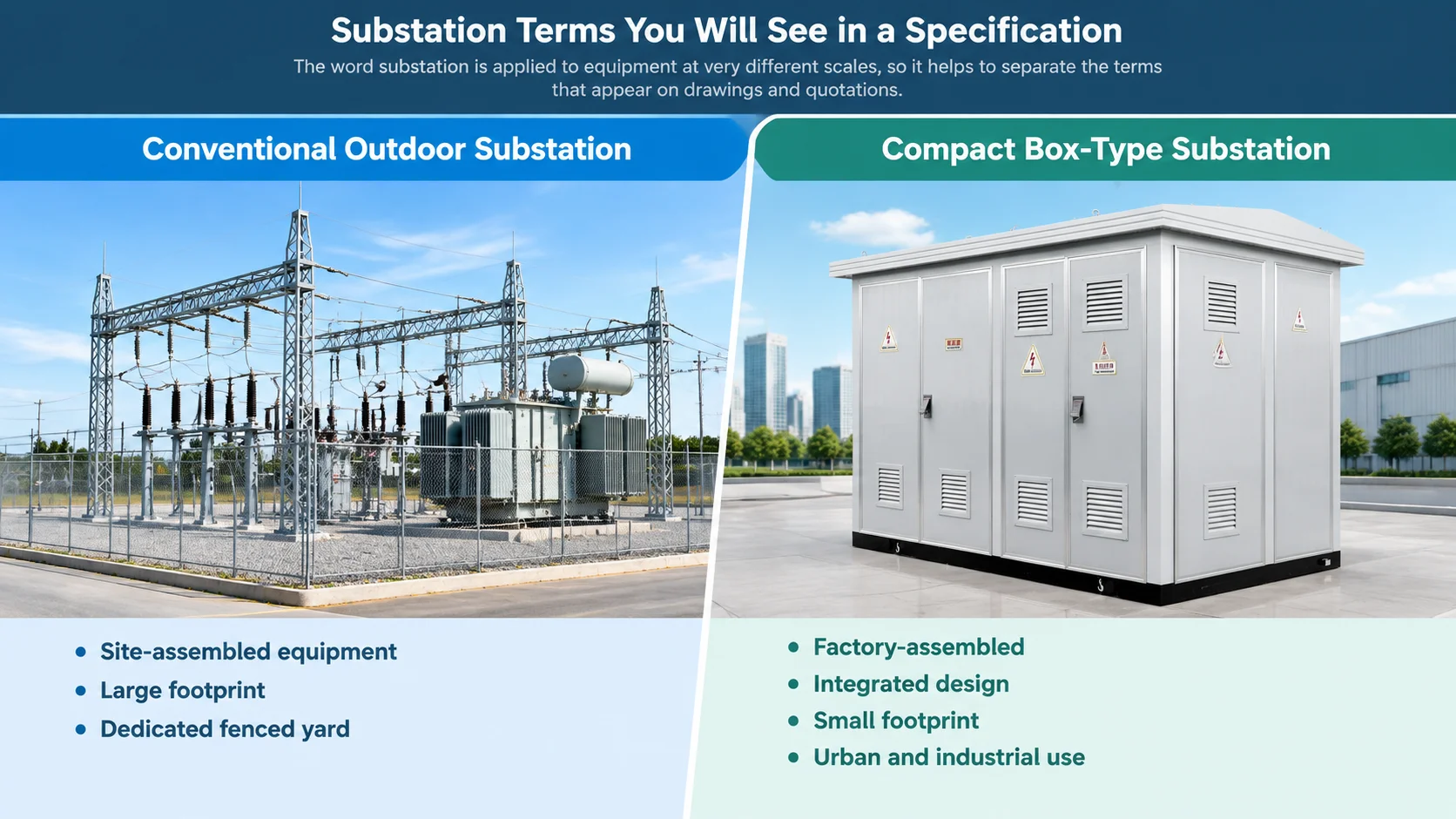
The word “substation” is applied to equipment at very different scales, so it helps to separate the terms that appear on drawings and quotations.
Conventional or open-air substation — equipment mounted on structures in a fenced yard, usually at higher voltages and larger ratings.
Compact or box-type substation — a factory-assembled outdoor enclosure that combines medium-voltage switchgear, a transformer and low-voltage distribution in a small footprint.
Package substation — another name for an integrated unit that supplies a complete distribution package from one enclosure.
Pad-mounted substation — a compact unit mounted on a concrete pad, common in underground residential distribution.
Ring main unit (RMU) — the medium-voltage switching section often found inside or alongside a compact substation. It is covered in more detail in the guide to what a ring main unit is .
Gas-insulated switchgear (GIS) — switchgear with live parts sealed in insulating gas, used where space or environment makes air-insulated equipment impractical.
How to Read Substation Ratings
Whether the site is a large transmission station or a compact distribution unit, a few ratings decide what the equipment can safely handle.
Rating
What it controls
Rated voltage
The system voltage class the equipment may be connected to
Rated current
The continuous load the busbars, switches and feeders can carry
Short-time withstand current
The fault current the equipment can survive while protection clears it
Peak withstand current
The first-cycle peak of the fault current
Power-frequency and impulse withstand
Insulation strength verified by dielectric and lightning-impulse tests
Enclosure protection (IP)
Protection against solid objects, dust and water at the installed location
Medium-voltage switchgear assemblies are commonly type-tested to standards such as IEC 62271-200, and the test certificates are the evidence that the ratings claimed for a design have been verified. Always confirm the ratings against the actual network fault level and load rather than assuming a standard value.
What to Check When Specifying a Substation
Work through these points before requesting quotations, because each one changes the configuration, the enclosure and the lead time.
System voltage and load. Match the voltage class and rated current to the network and the maximum continuous demand.
Fault level. Confirm the prospective short-circuit current so the withstand and protection ratings are adequate.
Transformer type and capacity. Choose oil-immersed or dry-type according to rating, indoor or outdoor location and fire considerations.
Switchgear and protection. Decide the number of ways, the switching devices and the relays required for the site.
Indoor or outdoor. Set the enclosure protection rating to suit the installation environment.
Automation. Specify metering, remote signalling and control where the unit will be monitored from a centre.
Standards and testing. Require type-tested equipment and ask for the relevant test certificates.
Site conditions. Confirm ambient temperature range, altitude and seismic requirements, since each can limit a standard rating.
Space and delivery. For compact units, check the transport route and lifting arrangements for the assembled enclosure.
For distribution-level projects, a factory-assembled prefabricated or box-type substation is often the practical choice, because the major equipment arrives pre-wired and the on-site work is reduced. An example is the YBM 10 kV integrated outdoor power distribution substation, which combines the medium-voltage section, transformer and low-voltage distribution in one outdoor enclosure and can be configured with an oil-immersed or dry-type transformer.
Frequently Asked Questions
What is the main purpose of a power substation?
Its main purpose is to change voltage so power can be transmitted efficiently and then delivered at a level that distribution equipment and customers can use. Substations also switch circuits, isolate faults and provide a point for metering and control.
What is the difference between a transmission and a distribution substation?
A transmission substation connects transmission lines and changes between transmission voltages, while a distribution substation reduces transmission or sub-transmission voltage to a medium voltage and sends it out on local feeders. Transmission substations usually operate at higher voltages and serve the bulk network; distribution substations sit closer to the customer.
Does every substation have a transformer?
No. A switching station operates at a single voltage level and switches lines without transforming, so it may contain breakers, disconnectors and busbars but no power transformer.
Are power substations dangerous?
Yes. Substations contain live conductors at high voltage, so access is restricted to trained, authorised personnel. Safety features such as earthing systems, interlocks, minimum clearances and locked enclosures reduce the risk, but the hazard never disappears.
Why are some substations outdoors and others indoors?
Indoor or enclosed substations are used in cities to reduce transformer noise, improve appearance, protect equipment from extreme climate or pollution, and save space. Outdoor installations are common where land is available and appearance is not critical.
What is a compact or box-type substation?
It is a factory-assembled outdoor enclosure that combines medium-voltage switchgear, a transformer and low-voltage distribution in one unit. It reduces the footprint and on-site work compared with a conventional substation, which makes it popular for industrial, commercial and renewable projects.
Key Takeaways
A power substation is a grid node that changes voltage and routes, protects and measures power between transmission and distribution. The main types — transmission, distribution, collector, converter, switching and mobile — are defined by the job they do, and almost all of them rely on the same core equipment: transformers, switchgear, instrument transformers, protection relays and an earthing system.
Once the system voltage, load, fault level and site conditions are known, the configuration and ratings fall into place. If you are planning a substation and want help matching a compact or box-type unit to your network, contact the SAGE Power team with your project details.
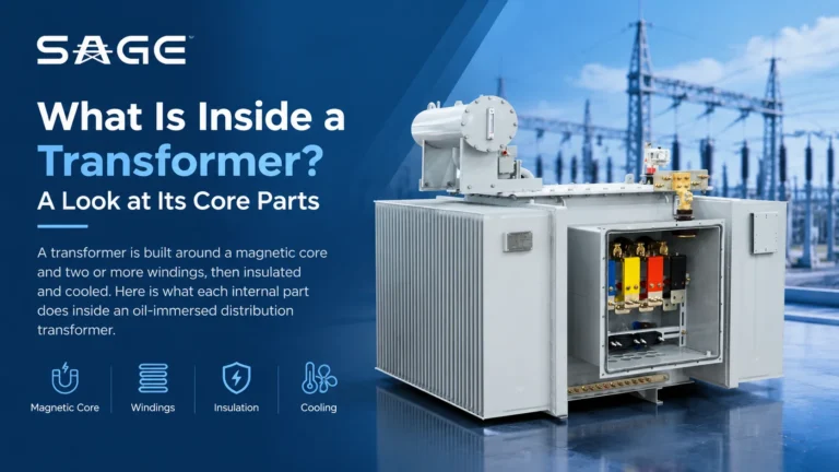
A transformer is built around a magnetic core and two or more windings, then insulated and cooled. Here is what each internal part does inside an oil-immersed distribution transformer.
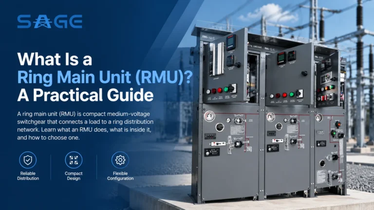
A ring main unit (RMU) is compact medium-voltage switchgear that connects a load to a ring distribution network. Learn what an RMU does, what is inside it, and how to choose one.