Insulated Plug Connector Buying Guide | Interface, Size and Installation
1. Identify the bushing interface and the cable size
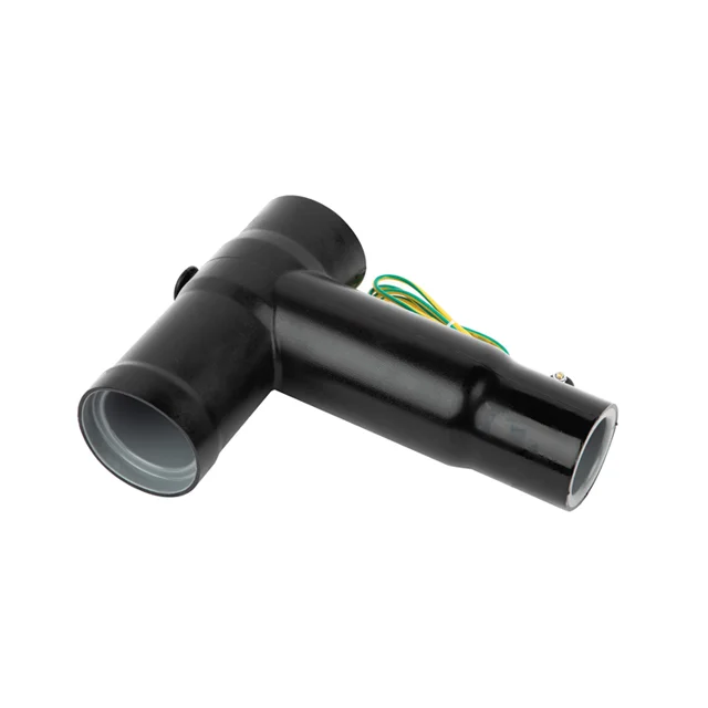
Separable connectors mate with a defined bushing interface, commonly described as size 1, 2 or 3 under EN 50181. Measure the bushing or read the switchgear drawing before ordering, because the interface size fixes the connector body. Then confirm the cable conductor size, the insulation diameter and whether the cable is copper or aluminium.
| Interface | Typical application | Note |
|---|---|---|
| Size 1 | Small cables and compact switchgear | Limited current rating |
| Size 2 | General 10kV and 24kV distribution | Most common for 630A |
| Size 3 | Large cables and higher currents | Check the bushing and the cable range |
2. Choose the rated voltage and current
Match the connector to the system voltage and the rated current of the circuit. A 630A connector on a 200A feeder is acceptable but unnecessary; a 200A connector on a 630A feeder is a fault waiting to happen. Confirm the short-time withstand current as well, because the connector carries the fault current until the protection clears it.
3. Select silicone or EPDM insulation
Silicone stays flexible over a wide temperature range and resists tracking, which suits outdoor and high-temperature locations. EPDM has good mechanical strength and resistance to moisture and ozone. Both work indoors; the choice follows the site temperature, the pollution level and the cable preparation method.
4. Plan the cable preparation and earthing
The cable cut-off point, the semiconductive layer and the stress cone must be prepared exactly to the instruction. A poor cut or a damaged semiconductive layer causes partial discharge and early failure. The copper screen and the armour must be earthed through the connector kit, and the earth connection must be sized for the fault current.
5. Confirm the kit contents and tests
A complete kit includes the connector body, stress cone, insulating plug, contact pin, earthing parts and the installation instruction. Routine tests cover dimensions, insulation and, where required, partial discharge. Ask for the kit list and the torque values, because missing parts stop the termination on site.
6. RFQ checklist
- System voltage and rated current
- Bushing interface size and switchgear model
- Cable type, conductor size and insulation diameter
- Silicone or EPDM insulation
- Indoor or outdoor installation and pollution level
- Kit contents, earthing and torque values
- Quantity, destination and delivery date
Send the cable schedule and the switchgear drawing and the correct kit can be confirmed in one round.